
A split AC wiring diagram is an essential guide for installing and maintaining air conditioning systems. It illustrates electrical connections between indoor and outdoor units, ensuring compliance with safety standards like NFPA70 and Canadian Electrical Code. These diagrams are crucial for technicians to understand the system’s layout, troubleshoot issues, and ensure efficient operation. They provide a clear visual representation of wiring, helping to avoid installation errors and promoting safe practices.
1.1 Importance of Wiring Diagrams for Split AC Systems
Split AC wiring diagrams are crucial for safe and efficient installation, maintenance, and troubleshooting. They provide a clear visual guide for technicians to understand electrical connections between indoor and outdoor units. These diagrams ensure compliance with safety standards like NFPA70 and Canadian Electrical Code, preventing installation errors and potential hazards. They act as a reference for diagnosing issues and ensuring system reliability, making them indispensable for technicians and installers.
1.2 Overview of Split AC Components (Indoor and Outdoor Units)
A split AC system consists of two main units: indoor and outdoor. The indoor unit includes the evaporator coil, fan motor, and air filter, circulating cooled air. The outdoor unit houses the compressor, condenser coil, and fan motor, managing heat exchange. Both units are connected by refrigerant lines and electrical wiring, working together to provide efficient cooling and airflow throughout the space.
Understanding the Basic Electrical Connections
Split AC systems require precise electrical connections to ensure proper operation. Power supply, wiring between units, and component connections must be accurately configured for safe and efficient functioning.
2.1 Power Supply Requirements for Split AC Systems
A stable power supply is crucial for split AC systems. Most systems require a single-phase 220-240V AC power supply. Ensure the wiring complies with NEC and uses copper conductors. The circuit should be rated for 105°C and connected to a 24VAC/40VA Class 2 circuit. Proper power connections are essential to prevent electrical hazards and ensure efficient operation.
2.2 Role of Capacitors in Split AC Wiring
Capacitors play a vital role in split AC systems by storing electrical energy to start and run the compressor and fan motors. They provide the necessary power surge for motor starting and help stabilize voltage fluctuations. Proper installation and replacement of capacitors are critical to ensure efficient operation and prevent potential system malfunctions or electrical hazards.
2.3 Compressor and Fan Motor Connections
The compressor and fan motor connections are critical for split AC operation. The compressor requires a secure connection to the capacitor and power supply, while the fan motor connects to the control board. Proper wiring ensures efficient starting and running of these components; Always refer to the wiring diagram for correct terminal connections and ensure wires are securely fastened to avoid electrical issues.

Safety Standards and Precautions
Adherence to NFPA70 and Canadian Electrical Code is mandatory. Always disconnect power before servicing, use copper conductors, and ensure secure connections to prevent fire hazards and electrical risks.
3.1 Compliance with NFPA70 and Canadian Electrical Code
Ensure all installations comply with NFPA70 and Canadian Electrical Code. Use specified wires, secure connections, and avoid inflammable environments. Disconnect power before servicing and verify conductor suitability for 105°C. Compliance prevents hazards and ensures system reliability, adhering to safety protocols and legal requirements for safe and efficient operation.
3.2 Essential Safety Practices for Installation
Always disconnect power before servicing. Use copper conductors and ensure connections are secure. Avoid installing in areas with inflammable gases; Verify conductor ratings for 105°C. Follow NFPA70 and Canadian Electrical Code guidelines. Use recommended wires and tools to prevent faults. Regularly inspect wiring for integrity to ensure safe and reliable operation of the split AC system.
Detailed Wiring Diagram for Single-Phase Split AC
A comprehensive guide detailing single-phase split AC wiring, including connections for indoor and outdoor units, power supply, and component links like capacitors and compressors, ensuring safe installation.
4.1 Indoor Unit Wiring Connections
The indoor unit wiring involves connecting power supply lines, thermostat wires, and communication cables. Ensure secure connections to terminals, following the diagram. Connect capacitors and fan motors according to specifications. Verify proper grounding and comply with safety codes like NFPA70. Double-check all wire connections to prevent short circuits. This ensures efficient operation and safety.
4.2 Outdoor Unit Wiring Connections
The outdoor unit requires connecting the compressor, fan motor, and capacitor. Securely attach wires to terminals, following the wiring diagram. Ensure proper power supply connections using copper conductors. Verify all connections are tight to prevent electrical issues. Comply with safety standards and local codes. Double-check the wiring before powering up the unit to ensure safe and efficient operation.
4.3 Interconnecting Wires Between Indoor and Outdoor Units
Interconnecting wires ensure communication and power flow between indoor and outdoor units. Use shielded cables to minimize interference. Connect wires securely to terminals, following the wiring diagram. Ensure proper insulation and routing to avoid damage. Verify all connections are tight to prevent signal loss or electrical issues. Adhere to manufacturer guidelines for wire specifications and safety standards.
Advanced Wiring Configurations
Advanced wiring configurations include three-phase systems and inverter technology integration, offering enhanced efficiency and precise temperature control. These setups require detailed diagrams for proper installation and troubleshooting.
5.1 Three-Phase Split AC Wiring Diagram
A three-phase split AC wiring diagram outlines connections for systems using three alternating currents. It details how to wire the compressor, fan motor, and capacitor, ensuring proper phase sequencing. This configuration is common in commercial settings, offering higher power efficiency. The diagram must be followed precisely to avoid electrical imbalances and ensure safe operation.
5.2 Inverter Technology Integration in Split AC Wiring
Inverter technology in split AC systems optimizes performance by adjusting compressor and fan speeds. Wiring diagrams for inverter models show connections for variable-speed drives, ensuring energy efficiency. These systems require precise wiring to regulate voltage and frequency, often using specialized control boards. Proper integration ensures smooth operation, reduced noise, and enhanced cooling capabilities, while maintaining compatibility with advanced inverter compressors.

Troubleshooting Common Wiring Issues
Common wiring issues include loose connections, short circuits, and capacitor failures. Using diagrams, technicians can identify faults, test components, and resolve problems efficiently, ensuring system reliability and safety.
6.1 Identifying Faults in Split AC Wiring
Identifying faults in split AC wiring involves checking for loose connections, damaged wires, and incorrect terminal links. Referencing the wiring diagram helps pinpoint issues like blown fuses or capacitor failures. Technicians can use multimeters to test voltage and resistance, ensuring accurate diagnosis and safe repairs. Regular inspections prevent major breakdowns and ensure optimal system performance.
6.2 Tools and Techniques for Diagnostic Procedures
Essential tools for split AC wiring diagnostics include multimeters, circuit testers, and thermal imaging cameras. Technicians use these to measure voltage, detect short circuits, and identify overheating components. Referencing the wiring diagram, they can trace connections and isolate faults efficiently; Proper techniques ensure accurate troubleshooting without causing further damage, promoting safe and effective repairs.

Manufacturer-Specific Wiring Diagrams
Manufacturer-specific wiring diagrams provide detailed layouts for brands like Daikin, Carrier, and Cooper&Hunter. These diagrams ensure compatibility and safety, tailored to each manufacturer’s unique system design and components.
7.1 Daikin Split AC Wiring Diagram
The Daikin split AC wiring diagram provides a detailed guide for installing and servicing Daikin systems. It includes specific instructions for connecting indoor and outdoor units, ensuring proper electrical connections and compliance with safety standards. The diagram highlights components like capacitors, compressors, and fan motors, offering a clear visual representation to facilitate smooth installation and maintenance processes effectively.
7.2 Carrier Split AC Wiring Diagram
The Carrier split AC wiring diagram is a detailed guide for installing and servicing Carrier air conditioning systems. It ensures compliance with NFPA70 and Canadian Electrical Code, providing step-by-step connections for indoor and outdoor units. The diagram highlights proper wiring for capacitors, compressors, and fan motors, ensuring safe and efficient operation. It also includes troubleshooting tips for common issues and specifies the use of correct wire specifications to prevent hazards.
7.3 Cooper&Hunter Split AC Wiring Diagram
The Cooper&Hunter split AC wiring diagram provides detailed instructions for installing and servicing their air conditioning systems. It outlines proper connections for indoor and outdoor units, ensuring compliance with safety standards. The diagram includes step-by-step wiring for capacitors, compressors, and fan motors, while emphasizing the use of correct tools and materials to ensure reliable operation and prevent potential hazards.

Installation Guidelines
Proper installation ensures safe and efficient operation. Mount indoor and outdoor units securely, connect wires according to the diagram, and ensure all connections are tight and insulated. Compliance with local codes and manufacturer specifications is crucial for reliability and safety.
8.1 Step-by-Step Installation Process
The installation process begins with preparing the site, ensuring proper placement of both indoor and outdoor units. Mounting brackets are secured, and units are carefully positioned. Power supply connections are made, adhering to the wiring diagram. Refrigerant lines are installed, and electrical connections are completed. Final checks ensure all components are secure and functioning correctly, with safety protocols followed throughout the process.
8.2 Securing Wires and Terminals for Long-Term Reliability
Properly securing wires and terminals is critical for long-term system reliability. Use copper conductors and ensure all connections are tightly secured to terminal blocks to prevent stress on wires. Verify that connections comply with NFPA70 and Canadian Electrical Code. Apply insulation to exposed terminals and regularly inspect wire integrity to prevent degradation or fire risks over time.
Compliance with Local Building Codes
Compliance with local building codes is essential for safety and legal adherence. Adhere to NFPA70 and Canadian Electrical Code standards, ensuring installations meet regional regulations and manufacturer-recommended practices.
9.1 Adherence to National Electrical Code (NEC)
Adherence to the National Electrical Code (NEC) is mandatory for safe split AC installations. NEC guidelines ensure proper wiring, grounding, and overcurrent protection, minimizing fire risks and electrical hazards. Compliance with NEC standards is crucial for legal and safety reasons, protecting both personnel and equipment during installation and operation.
9.2 Local Regulations for Split AC Installation
Local regulations for split AC installation vary by region and must be strictly followed. These regulations often include specific requirements for permits, inspections, and compliance with area-specific electrical codes. Ensure all installations meet local standards to avoid legal issues and ensure safety. Compliance with local regulations guarantees proper system functionality and longevity, adhering to community-specific safety protocols.

Maintenance and Upkeep
Regular maintenance ensures optimal performance and longevity of split AC systems. Inspect wiring, clean filters, and check connections to prevent issues. Secure all components tightly to avoid loose connections and ensure safe operation, maintaining efficiency and reliability over time.
10.1 Regular Checks for Wiring Integrity
Regularly inspect wiring for signs of wear, fraying, or damage to ensure system reliability. Verify all connections are secure and meet the specifications outlined in the wiring diagram. Check for loose terminals, corrosion, or heat damage, which can cause electrical failures. Use appropriate tools to test for continuity and ensure no short circuits exist. This proactive approach prevents unexpected breakdowns and maintains safety standards, ensuring your split AC operates efficiently and effectively. Regular inspections also help identify potential issues before they escalate, reducing repair costs and extending the system’s lifespan. Always refer to the wiring diagram for accurate guidance during inspections. Proper maintenance ensures optimal performance and minimizes risks associated with faulty wiring. By adhering to these checks, you can uphold the integrity of your split AC system and enjoy consistent cooling throughout the year. Additionally, keeping the wiring clean and free from debris contributes to better airflow and energy efficiency. Remember, regular checks are a small investment that pays off in the long run by preventing major issues and ensuring your system runs smoothly for years to come. Always disconnect power before performing any inspections to ensure personal safety and avoid accidental start-ups. Using the correct tools and following safety protocols is essential during these checks. By maintaining wiring integrity, you not only preserve the functionality of your AC but also protect your home from potential hazards. Stay vigilant and schedule regular checks to keep your system in top condition. This commitment to maintenance will reward you with a reliable and efficient cooling system that meets your needs without unexpected interruptions.
10.2 Best Practices for Extending System Lifespan
To extend the lifespan of your split AC system, ensure proper installation and regular maintenance. Use high-quality wires and components, and follow the wiring diagram precisely. Keep the system clean, and check for wear or damage regularly. Avoid overloading circuits, and ensure all connections are secure. Maintain proper airflow and keep the outdoor unit protected from harsh weather conditions. Regular servicing and timely repairs will enhance efficiency and durability, ensuring optimal performance for years. By adhering to these practices, you can minimize wear and tear, reduce energy consumption, and prolong the system’s operational life effectively. Proper care and attention will significantly contribute to the longevity and reliability of your split AC system, ensuring it continues to provide consistent cooling without unnecessary breakdowns or premature replacement. Consistent maintenance also helps in maintaining warranty compliance and reduces long-term operational costs. Always refer to the wiring diagram for guidance on best practices tailored to your specific system. This approach ensures your split AC remains in excellent condition, delivering reliable service and maintaining your comfort without interruptions. Regular filter cleaning, coil maintenance, and drainage checks are also vital for sustaining system health and efficiency. By combining these practices, you can maximize the lifespan of your split AC and enjoy uninterrupted cooling for many seasons.

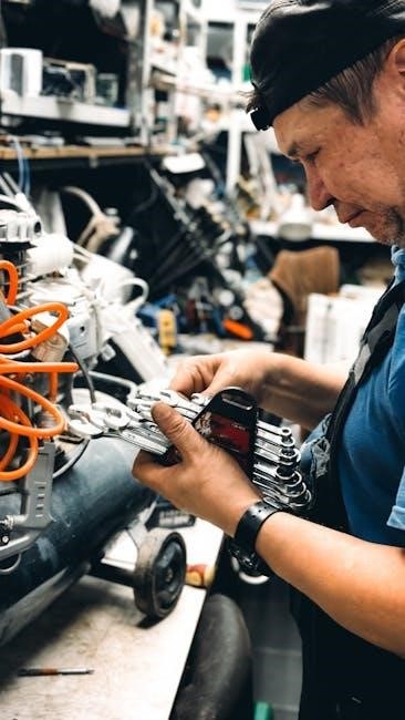
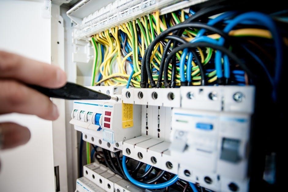
Tools and Materials Required
Essential tools include multimeters, wire strippers, pliers, screwdrivers, and circuit testers. Use high-quality copper wires, connectors, and insulation materials as specified in the wiring diagram for safe connections.
11.1 Recommended Wire Specifications
Use copper conductors suitable for 105°C, as specified in the wiring diagram. Ensure wires meet ampacity requirements and overcurrent protection ratings from the unit’s rating plate. Compliance with NEC and Canadian Electrical Code is mandatory for safe installations. Always refer to the manufacturer’s guidelines for wire sizing and material specifications to ensure reliability and efficiency.
11.2 Essential Tools for Safe and Efficient Wiring
Essential tools include a multimeter for voltage checks, wire strippers for safe wire preparation, screwdrivers for terminal connections, pliers for gripping wires, and safety gear like gloves. Use a crimping tool for secure connections and a thermometer for verifying operation parameters. Ensure all tools meet industry standards to guarantee safe and efficient wiring practices, as outlined in the wiring diagram manual.
12.2 Final Tips for Working with Split AC Wiring Diagrams
A split AC wiring diagram is crucial for safe and efficient installation. Always follow safety standards, use proper tools, and ensure compliance with local codes for reliable operation.


About the author